Hacking the MV1

@Drew @Peter
DISCLAIMER:
I don’t work for MARSFfarm, so this is not a recommended procedure, and will probably void all warranties, and may lead to magical blue smoke.

I have been running a ‘breadboard’ version of the MV1 to test code and new sensors. It has most of the MV1 code, but blinks LEDs on the breadboard instead of actually actuating pumps and heaters (and has no plants!). In addition I use it to test new sensors.
I wanted to move some of this to the actual MV1, and make a few changes to the camera (for OpenCV purposes), but have felt limited by the Raspberry Pi W (too slow for a full GUI and development). So a while back I pulled the W and plugged a ribbon cable from the MV1 to a Raspberry Pi 3B. After moving over the SD card, it booted up and worked as if nothing had changed. I temporarily hooked up a keyboard and monitor, and turned on the setting for VNC (so I could access the Pi via my laptop).
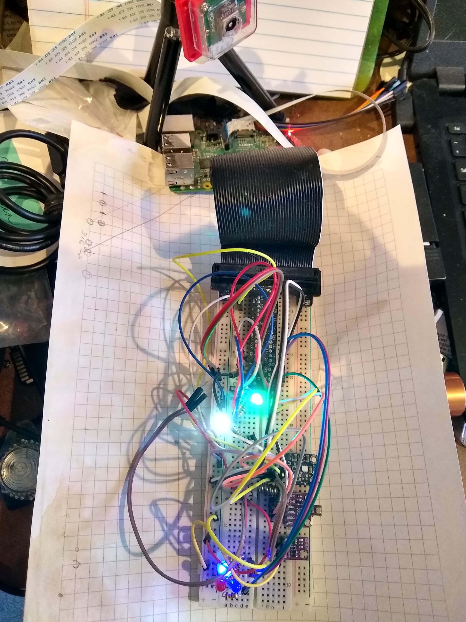
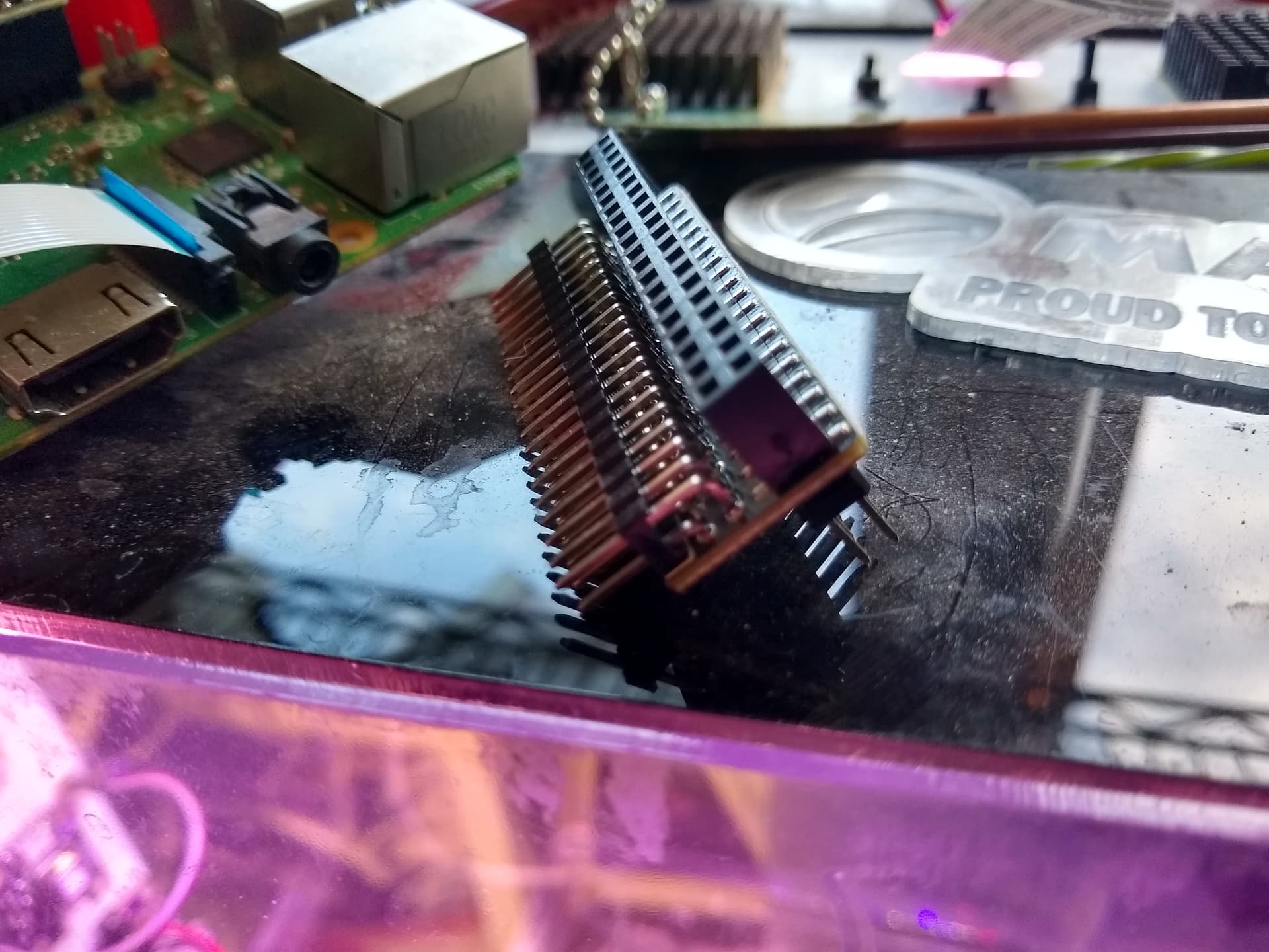
The next step was to get ahold of the GPIO pins for adding I2C sensors. For this got GPIO expansion pins, that allowed me to add a second ribbon cable (attached to a breadboard).
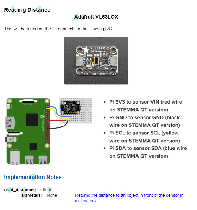
With some changes to the LogSensors.py file, I now have additional BMP280, BME60 and SCD40 sensors for temperature, humidity, barometric pressure and CO2. My charts now show sensor comparisons!
The photo shows the Raspberry Pi precariously sitting on top of the MV1, with two ribbon cables coming off of it, and the breadboard hanging in the box.

1 Like

To be clear, we gave you MV1-HQ1, which doesn’t even have a serial plate - it never had a warranty lol.

@hmw would you please share a few more photos of the breadboard and the actual connections? Maybe a quick pencil sketch/diagram on paper? I’m a little confused about how you ‘breakout’ the wires into the breadboard in particular. Honestly, I tried to do this once and got mixed up with my wires and this use case (upgrading the microprocessor on an MV1) isn’t unheard of @Surendra @cregini with customers.

If I’m not mistaken, the origin

This would also be cool to talk more about - you’re essentially creating a ‘trainer’ or a ‘testing’ unit for learning about the MV1. A much smaller scale of these products used for teaching HVAC technicians/electricians:


image

@Peter
This is my breadboard version of the MV1. Most projects start out as breadboard projects, for the ease of making changes. Below is a picture of my breadboard, with a ribbon cable running from the Raspberry Pi to the breadboard “T” adapter. A lot of these adapters come labeled with the use of the GPIO.
Fans and heater are substituted with LEDs, and the light panel is substituted with a RGB LED and a white LED. All GPIO pins remain the same, and there is no need to change the code, as the LEDs can work off of straight 3V, or via the PWM (light panel), though there is no need for the power supply. Wires get a little messy, but this is an economic way to test code and sensors, without the expense of the full box. I use this setup for testing cameras and new sensors.

1 Like

Here are some more details about my Raspberry Pi 3B breakout on the MV1. This approach is to minimize the physical and program changed needed for the MV1.
Initially I just wanted to have a Pi B+ instead of the Zero (something with more power to support VNC and the full desktop). With just one ribbon cable, this was basically just a brain transplant.
For the breadboard, I needed a second cable. This second cable works like any other breadboard project.

There is a nice connector that makes this double cabling easy.


The top cable goes to the MV1, the one off the side

One cable goes off to a breadboard, the other simply connects to the MV1 where the Raspberry Pi Zero was plugged (all Raspberry Pis have the same 40 GPIO pin arrangement).

The only caution is to make sure the orientation of the cables matches - this is best checked with a multi-meter (check for the 3V output pins). The orientation is fairly intuitive if you have any experience with breadboard projects with a Pi.

At this point you can ignore the MV1, as everything works the same as when the Zero was directly connected. Be sure to work with the config.py file, as it defines the MV1 use of pins. Since I am only adding I2C sensors, I can simply use the pre-defined pins, but access them via the breadboard (the all trace back to the same pin on the Pi). Since I2C sensors are separately addressed, they can be wired together, either in serial or in parallel. Any GPIO not defined in config.py is available to be used for new projects. I would suggest documenting any new pins in the config.py file, noting them as custom additions.
The cables are strong enough that I just threaded the cable between the wall and the top (after temporarily removing a corner screw), and let the breadboard hang in the box.


In this case I have three sensors: SCD40 CO2 sensor, BMP280 (temp, humidity, pressure) and a BME680 (temp, humidity, pressure, gas).
One side of the breadboard supplies 3V power, the other 5V power. The SCD40 works best off of 5V.
I added the new sensor files to the python directory, and added some new functions in LogSensors.py to call these sensor functions.

1 Like

@hmw We had hacked the old GBE units a while back. It began with needing more reliable watering capabilities and then took on a life of its own from there. It runs on a Pi 4, soon to be 5, and we have laser cut the walls to custom mount sensors we wanted to incorporate. I now have a fleet of about six that I use as training modules for students to learn how to wire and program their environments. I’ve written my own library for the purpose of abstracting the nuances of working with each sensor. Here are some pictures of the units along with some documentation about the sensors we like to use. Getting to a point where the MV1 could incorporate a bring your own sensor type feel would be really neat!

Sensor Documentation

1 Like

That is definitely modified!!

1 Like

First of all, this is extremely cool - thank you both for sharing. For this level of prototyping (hardware) @hmw is pretty much our first tier of R&D (testing new sensors, cameras, writing/upgrading/testing that level of firmware, etc.) and @cregini you’ve been hacking away at Food Computers just as long as we have - it’s very cool to see all of this here.

We have an open GPIO pin on the MV1 that’s already set up to an open/unused plug - I’d need to look back into what all you could install onto that. I’m curious if Atlas would want to collaborate on that - we’d be down to work with them. Frankly, I have no desire whatsoever to design sensors for a liquid environment and deal with calibration/storage/etc. We want to encourage users to add on extra sensors and would even work together on designing a front-end interface for them too.

Few questions (no rush, just curious):

2a - What’s the color sensor for? For reading cards/samples or something?


3a - where does this VL53LX sensor go - I saw it in the documentation and didn’t know if this was still to be installed, curious to know if it works.

I can only speak from my own experience, but I think the quickest way to opening up external sensors would be to make an i2c bus available. That’s the communication protocol used for interfacing our Atlas Scientific sensors. They are more expensive that a lot of others out there, but their calibration, storage, and python documentation is very solid and there is a preexisting i2c library out there on GitHub.

1a. The time of flight sensor you ask about later in the post is found mounted right next to the camera on the top of the unit. It is used to determine how far away objects in front of the camera are located. It is actually very accurate, but the objects do need to be directly in front of the lens as it emits a narow band of light.

1b. The camera we are using is the latest to be released from the Raspberry Pi Foundation.

The color sensor can be used for a number of different reasons. Determining the color of cards placed in the field of view for computer vision is one we are looking into. The other is just for quantifying “green” with respect to plant health inside the box. We had a student do a research project on the effects of certain additives to hydroponic reservoirs and they wanted a way to quantify color observations. We have since purchased some higher level equipment to achieve this.

@Peter @cregini
I have not seen the Raspberry Pi 3 camera. Arducam has one almost the same, but I suspect the Raspberry will work with libcam straight out of the box and not require the configuration tweaks that Arducam requires.
Years ago I played with TLF (time of flight) sensors, but back then they were IR. Interesting to see cheap real Laser sensors (VL53LOX) have now become. I was trying to use one to determine the amount of water left in a reservoir, may have to take another look at that project.

@cregini
If you have a color card, why do you need the color sensor? With the known color values of the card, it should be possible to color correct an image, which would then give you consistent and known color values of a plant.
Of course, I am sure you can find a number of other uses for a sensor like this.

@hmw
Perhaps I didn’t clearly explain the use of the color sensor. You are correct about the color cards. We are not quite there yet, or perhaps I should say “I” am not there yet, with reliably deploying CV in my projects.

In lieu of color cards and programming the camera to quantify color, we use this sensor with clippings from the plants in the box to help students take color readings.